OpenGL's Graphics Pipeline
In my last post, I created a small project and got a blank window to show up. Throughout that whole process, the only real OpenGL function we used was glViewport to handle resizing the space that OpenGL can render to. Today I plan on doing some actual rendering, by getting a triangle on the screen.
OpenGL has 6 main stages in its main graphics pipeline:
- Vertex Shading
- Geometry Shading
- Shape Assembly
- Rasterization
- Fragment Shading
- Tests and Blending
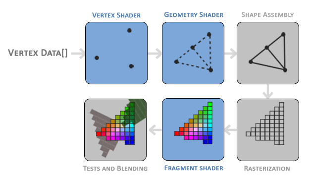
Image Source: leanopengl.com
I'm not going to talk about what each stage does since it's explained in pretty good detail on learnopengl.com. Each part in this pipeline is a step to turn vertex data into a pixel in our window. We're able to program the Vertex Shading, Geometry Shading and Fragment shading parts of this process. However, only Vertex Shading and Fragment Shading are required.
Window Buffer
Before rendering our first shape, one more thing that I forgot to do in my last post. Learn OpenGL shows how to set the window background colour to be something other than black, so that's what I'm going to do here. It only takes 2 calls in the main render loop.
while (!glfwWindowShouldClose()) {
glClearColor(0.106f, 0.035f, 0.122f, 1.0f); // Sets colour to clear buffer with
glClear(GL_COLOR_BUFFER_BIT); // Clears buffer with last set colour
glfwSwapBuffers(window);
glfwPollEvents();
}We now have our window looking like this: 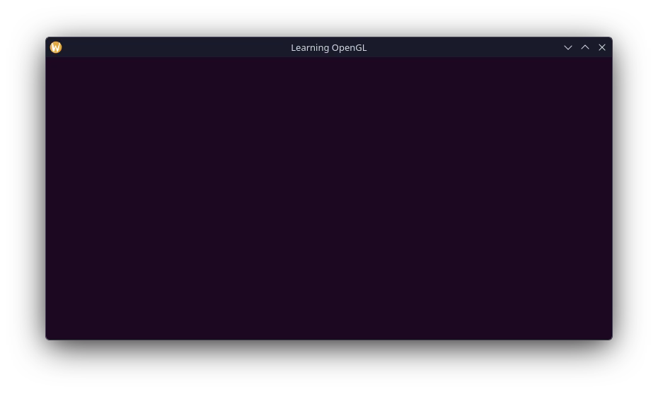
Vertex Data
First step is defining the vertices of the triangle, the coordinates of which are 3D and each axis ranges between -1.0 and 1.0. These coordinates are "normalized device coordinates". Anything outside of that range is simply not rendered to the screen. The screenspace coordinates are then achieved by transforming the normalized device coordinates using the values set with glViewport.
float32 vertices[] = {
-0.5f, -0.5f, 0.0f,
0.5f, -0.5f, 0.0f,
0.0f, 0.5f, 0.0f,
};This data is send to the first stage in the graphics pipeline, the vertex shader. Since the vertex shader runs on the GPU, we need to first allocate GPU memory in which to store out vertices.
uint32 vertexBufferObject;
glGenBuffers(1, &vertexBufferObject);This doesn't strictly allocate the memory, creates a buffer object and an identifier for a single buffer that we store in vertexBufferObject.
Next is to move our vertex data into the buffer object. To do that we first need to bind the buffer, so that we can operate on it, and then we can move the data to it. Since we are only trying to draw a static triangle, we can do this outside of the main render loop and also provide a usage hint that its a static drawing.
glBindBuffer(,);
glBufferData(, sizeof(),,);Shading
Vertex Shader
To actually render our triangle, we need to create a vertex and fragment shader. Our vertex shader can be simple, and just re-emit the coordinates given. Shaders are written in GLSL, and the vertex shader I will use looks like this:
#version 330 core
layout(= 0) in vec3 aPos; // location important for later
void main() {
gl_Position = vec4(aPos.x, aPos.y, aPos.z, 1.0);
}Since I'm only learning here, I'll be embedding the shader source into my actual source file as a string literal. Of course in a practical environment I'd write some asset system, which I may do later.
const int8 *vertexShaderSrc =
"#version 330 core\n"
"layout(location = 0) in vec3 aPos;\n"
"\n"
"void main() {\n"
" gl_Position = vec4(aPos.x, aPos.y, aPos.z, 1.0);\n"
"}\0";Similar to the buffer object previously declared, shaders also get given an ID. And then using this shader source we can compile it.
uint32 vertexShader = glCreateShader(GL_VERTEX_SHADER);
glShaderSource(vertexShader, 1, &vertexShaderSrc, nullptr); // null terminated, no length needed
glCompileShader(vertexShader);Of cource, shader compilation can fail, so we should appropriately check that compilation succeeds and report any errors.
{
int32 success;
int8 infoLog[512];
glGetShaderiv(vertexShader, GL_COMPILE_STATUS, &success);
if (!success) {
glGetShaderInfoLog(vertexShader, 512, nullptr, infoLog);
fprintf(stderr, "Vertex shader compilation failed.\n%s", infoLog);
return -1;
}
}Fragment Shader
The process for setting up and compiling the fragment shader is largely the same. As for the actual shader we specify a colour for the end pixel to be.
#version 330 core
out vec4 FragColor;

void main() {
    FragColor = vec4(0.941, 0.973, 1.0, 1.0);
}
Super simple, we're just setting the fragment's colour to be a slightly off-white. As previously, the compilation is largely the same, except we specify this is a fragment shader.
uint32 fragShader = glCreateShader();
glShaderSource(, 1, &fragShaderSrc,);
glCompileShader();
{
int32 success;
int8 infoLog[512];
glGetShaderiv(fragShader, GL_COMPILE_STATUS, &success);
if (!success) {
glGetShaderInfoLog(fragShader, 512, nullptr, infoLog);
fprintf(stderr, "Fragment shader compilation failed.\n%s", infoLog);
return -1;
}
}Shader Program
Now that we've compiled the shaders, they can be used to construct a shader program. This is the part that we will actually set what series of shaders are used to render the triangle. As with almost everything before, we need and ID for it. We can then easily add our compiled shaders, and then link them.
int32 shaderProgram = glCreateProgram();
glAttachShader(,);
glAttachShader(,);
glLinkProgram();This stage can fail as well, check and log for any errors:
{
int32 success;
int8 infoLog[512];
glGetProgramiv(shaderProgram, GL_LINK_STATUS, &success);
if (!success) {
glGetProgramInfoLog(shaderProgram, 512, nullptr, infoLog);
fprintf(stderr, "Shader program link failed.\n%s", infoLog);
return -1;
}
}Now that we have a linked shader program, we can safely dispose of the shaders.
glDeleteShader();
glDeleteShader();Drawing A Triangle
We should be just a few steps from drawing our triangle now. In our main render loop, we need to tell OpenGL to use our shader program. Afterwards we need to link up the vertex attributes so OpenGL knows how to interpret the data we provide the shaders. This is where the location attribute in our vertex shader is used.
Telling OpenGL to use our shader program is just a single function call in our render loop.
while (!glfwWindowShouldClose()) {
glClearColor(0.106f, 0.035f, 0.122f, 1.0f); // Sets colour to clear buffer with
glClear(GL_COLOR_BUFFER_BIT); // Clears buffer with last set colour
glUseProgram(shaderProgram);
glfwSwapBuffers(window);
glfwPollEvents();
}Next, configuring the vertex attributes, which we do immediately outside of the render loop, before we enter it.
// First arg pertains to the location set in the shader, thats where the coords are going.
glVertexAttribPointer(0, 3,,, 3 * sizeof(),);
glEnableVertexAttribArray(0);Vertex Array Object
The last thing we need to declare is the vertex array object, it can be thought of as like a map as to where all the data being bound ends up. It's quite tricky to explain for me, but that's about the best I can summarise at the moment.
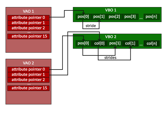
Image Source: Learn OpenGL
We can create the vertext array object (VAO) similarly to how we made the vertex buffer object, and then bind it so it is properly associated with the VBO when we bind the data afterwards.
glGenVertexArrays(1, &vertexArrayObject);
glBindVertexArray();Then before the render loop, for extra safety, we can unbind the VBO and VAO so its not accidentally modified. This shouldn't happen to be clear, but doesnt hurt to add some railings to our catwalks.
glBindBuffer(, 0);
glBindVertexArray(0);The Moment You've Been Waiting For
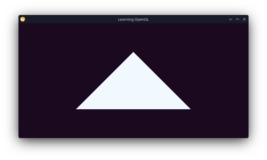
We can now FINALLY draw our triangle, we've already set the shader program to use, now we bind our VAO (again, since we unbound it) and make our draw call.
while (!glfwWindowShouldClose()) {
glClearColor(0.106f, 0.035f, 0.122f, 1.0f); // Sets colour to clear buffer with
glClear(GL_COLOR_BUFFER_BIT); // Clears buffer with last set colour
glUseProgram(shaderProgram);
glBindVertexArray(vertexArrayObject);
glDrawArrays(GL_TRIANGLES, 0, 3);
glfwSwapBuffers(window);
glfwPollEvents();
}And here is what we get!